Ultrasonic Testing (UT)

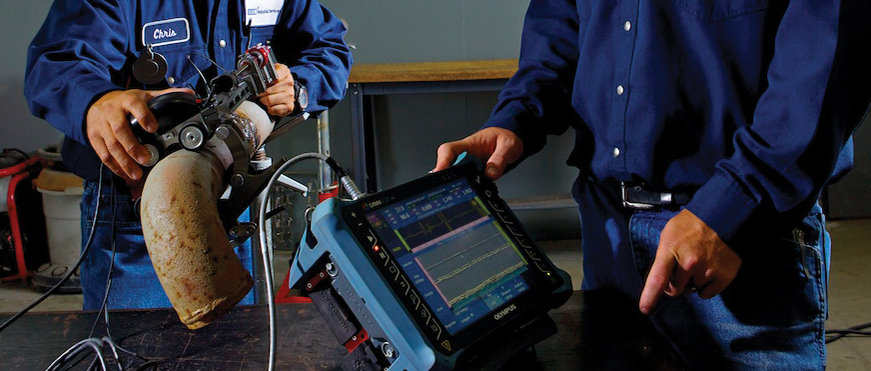
Ultrasonic Testing (UT) uses high frequency ultrasonic waves to detect surface breaking and internal imperfections, measure material thickness and determine acceptance or rejection of a test object based on a reference code or standard.
Ultrasonic Thickness Testing (UTT)
Our UTT measures remaining wall thickness on piping, pressure vessels, storage tanks and other materials, and can be used to scan bolts, shafts and raw materials for imperfections. A straight beam is directed at the test piece and, utilizing the round trip time for the ultra- sonic energy, the distance to the flaw is displayed in thousandths of an inch. On UT units with A-scan, the display will show multiple flaws at different depths.
Shearwave Ultrasonics (UT-S)
Our UT-S or A-scan testing transmits an ultrasonic wave at a predetermined angle into the test material. Surfaces normal to the beam path and corner traps reflect the wave energy back to the transducer. The display shows the distance the wave traveled to the imperfection and the relative strength of the energy.
B-Scan
Our B-scan is useful for corrosion analysis or locating laminations and inclusions in new rolled materials. Real-time imaging displays a profile of the test material along the scan path. Images can be stored for later review.
C-Scan
Our C-scan can be used to determine corrosion rates and code calculations. The inspection is done in an immersion tank or with a tank crawler, and data is displayed on a plane view utilizing a color system to indicate various material thicknesses.
Internal Rotating Inspection System (IRIS)
Our IRIS inspection detects defects and measures wall loss of both ferrous and nonferrous tubing. It provides information about the geometry of the defect while accurately measuring local defects and wall loss on both the inside and the outside of a tube. Defects under support plates are easily detected and quantified as well. Computerized reporting and tube sheet mapping are available.
Time of Flight Diffraction (TOFD)
Ideal for inspecting and sizing defects in welds, our TOFD uses two angled probes (one on each side of the weld) to transmit sound waves into the test material at angles specific to its thickness. Discontinuities are shown as breaks in the waves or as additional waves between mode lines. TOFD is normally utilized in conjunction with Phased Array UT.
Guided Wave Testing
Our advanced Guided Wave inspection services enable you to locate pipe defects above and below ground without disruption of service.
TEAM can help your company:
- Provide instant and accurate results
- Detect surface breaking and internal imperfections
- Measure material thickness
- Determine imperfections throughout the entire material thickness, and may be used with access to only one surface
- Determine acceptance or rejection of a test object based on a reference code or standard